Saturday, March 26, 2016
V-Curves and Inverted V-Curves of Synchronous Motor
A synchronous motor is a double-excited machine, its armature winding is energized from an a.c source and its field winding from d.c source.Synchronous motor operates at unity power factor when field current is enough to set up the air-gap flux, as demanded by constant applied voltage.This field current, which causes unity power factor operation of the synchronous motor, is called normal excitation or normal field current.

What are V and inverted V curves ?
- V-curve is a graph between Ia Vs If.
- Inverted V curve are drawn between cosΦ Vs If.
In the above two cases If (field current) taken on x-axis.We can control the field excitation of synchronous motor by increasing/decreasing the field current.

 From above values make a final table like this,
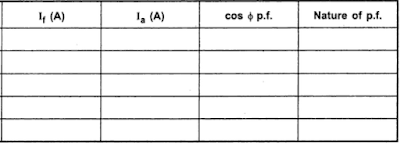
The graph can be plotted from this result table.
1) Ia Vs If → V-curve
2) cosΦ Vs If → Inverted V-curve
This is the entire procedure can be repeated for various load conditions to obtain of V-curves and Inverted V-curves of any synchronous motor.
Tags: v and inverted v curves of synchronous motor wikipedia,v and inverted v curves of 3 phase synchronous motor
Experiment to Obtain V-Curves and Inverted V-Curves
If graph of armature current drawn by the motor (Ia) against field current (If) is plotted, then its shape looks like alphabet V. If the power factor (cos Φ) is plotted against field current (If), then the shape of the graph looks like an inverted V.

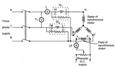
v and inverted v curves of synchronous motor circuit diagram
- Connect stator of motor to 3 phase supply as shown in the above figure through watt meters and ammeter.
- In this experiment two watt meter method is used to measure input power of motor.Ammeter reads the line current which is same as armature (stator) current. Voltmeter is reads line voltage.
- A rheostat in a potential divider arrangement is used in the field circuit to control the excitation.By changing its value note down the voltage,armature current,watt meter readings(W1&W2) in a table like below.
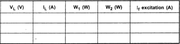
Now IL = Ia, per phase value can be determined, from the stator winding connections.
IL = Iaph for stator connection
IL/√3 = Iaph for delta connection
The power factor can be obtained as

The graph can be plotted from this result table.
1) Ia Vs If → V-curve
2) cosΦ Vs If → Inverted V-curve
This is the entire procedure can be repeated for various load conditions to obtain of V-curves and Inverted V-curves of any synchronous motor.
Tags: v and inverted v curves of synchronous motor wikipedia,v and inverted v curves of 3 phase synchronous motor